
One of the challenges facing designers of lighting fixtures or luminaires that use high-brightness LEDs (HBLEDs) is testing the low-voltage, constant-current power supplies, called drivers, used to power the LEDs. Making this choice is difficult because the number of LEDS and the configuration of the LEDs will vary from design to design.
To test HBLED drivers to determine if they are suitable for a particular application, designers need a flexible, programmable load to simulate different LED configurations. This is especially true when the LED assembly for a particular fixture is not yet available. The test system needs to not only simulate the proper operation of LEDs connected in series or parallel, but also failure modes, such as shorted or open diodes in a series string.
Programmable electronic loads, or eLOADS, make excellent HBLED load simulators. AMREL electronic loads have a standard feature, called V(on) or under voltage lockout protection (UVL), that designers can use to simulate the forward turn on voltage of an HBLED string. The load’s constant resistance control is then used to set the nominal operating point. Multiple loads can be used to simulate complex parallel string and matrix configurations.
A simple application
To show how this works, we use a standard lab power supply to simulate an HBLED driver. To simulate a string of HBLEDs connected in series, we simply connect an AMREL programmable load across the output of an HBLED driver.
In this case, the LED string to be simulated has a forward voltage threshold, V(fwd), of 40 VDC, an operating voltage, V(op) of 42.2 VDC, and and operating current, I(op), of 3 A. To simulate the forward threshold voltage of the string, we used the V(on), or under voltage lockout protection (UVL), feature of the load. This function allows the user to set a trigger point between 0 V and the load’s full-scale voltage rating. The load will remain off until the input voltage reaches V(on).
This feature has two modes. In “continuous” mode, load will turn on when the input voltage is greater than V(on) and turn off when the input voltage drops below this value. In the “input on” mode, the load will also turn on when the input voltages exceeds V(on) and turn off when the input voltage drops below this value, but it will remain off even if the voltage rises above V(on) until the input is cycled.
To determine the value that you must set the electronic load to when it is operating in constant resistance mode, you simply divide the operating voltage by the operating current:
R = V(op)/I(op) = 42.2V/3A = 14 Ω
For this demonstration, we set the programmable power supply output to 45 VDC and to operate in constant current mode at a current of 3 A.
Results
Figure 1 shows how the electronic load simulates diode behavior. Trace 1 shows the current through the load. Trace 2 shows the output voltage of the power supply. After the supply is turned on, the output voltage rises until it reaches the V(on) set point. At that point, the electronic load turns on, and the current rises to the LED string’s operating point.
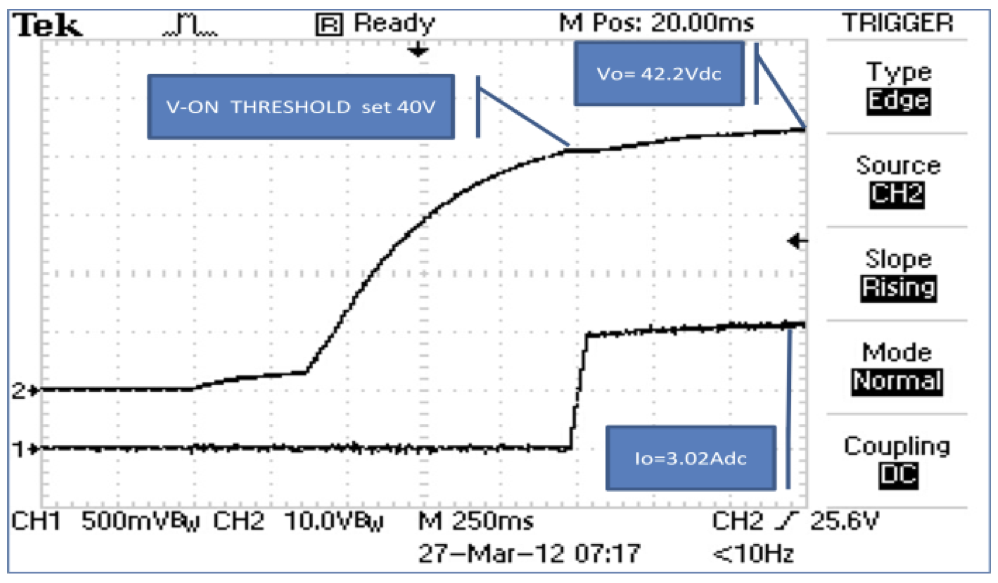 This oscilloscope screen shot shows how the UVL feature of AMREL's electronic loads allow you to simulate HBLEDs.
To simulate more complex HBLED configurations, such as a matrix configuration or parallel string, you can use more than one electronic load. To simulate shorted or open circuits, you can program individual electronic loads to toggle between various resistance values and then observe the behavior of the driver under test. Whatever your needs, using off-the-shelf instruments make it much easier to configure your test setup.