
When a load draws a high current, the voltage drop across the power leads could be high enough to cause a device under test (DUT) to fail or cause a system to malfunction. The solution to this problem is to use remote sensing. By adding a second set of wires—the sense wires—you can ensure that the proper voltage level is at the DUT or system's power terminals.
To calculate voltage drop across the power leads, you simply multiply the current being drawn by the load by the resistance of the leads. Table 1 shows some typical voltage drops. For example, if you are using 14 gauge power leads, and drawing the maximum 15 A, the voltage drop across a 100-ft. length will be 3.85 V. The voltage drop across a 10-ft. power lead will be only 0.385 V, but that is still substantial in some applications.
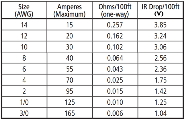 Table 1. Resistivity and IR drop for common cable sizes.
To compensate for this voltage drop, you use a feature called remote sensing. When using the remote sense feature, a power source will regulate the output voltage based on the voltage present at its remote sense inputs rather than the voltage present at its output terminals. The source's output will be higher than the voltage required by the load to compensate for the voltage drop across the power leads.
To use the remote sensing feature, you add a second set of wires—called sense lines—from the power source to the load. As shown in Figure 1, connect the sense cables to the power input terminals at the load and to the Remote Sense inputs at the power source. In addition, connect one end of the cable shield to ground close to the sense connector. The other end does not need to be connected.
Choosing the right cables
Remote sense inputs typically have an input impedance of 1kΩ. This means that the sense lines carry very little current and the voltage drop across them is very low. When choosing a wire gauge for the sense lines, ensure that the voltage drop across them is less than 100 mV. Typically, 24 AWG to 18 AWG will be required.
To minimize noise pickup or radiation from load circuits, power leads and remote sense wires should be shielded, twisted pair cables, as shown in Figure 1, that are as short as possible. Using twisted pair cables not only helps prevent noise pickup, but it also reduces coupling between the power leads and sense lines. Shielding of the sense leads may be necessary in high noise environments.
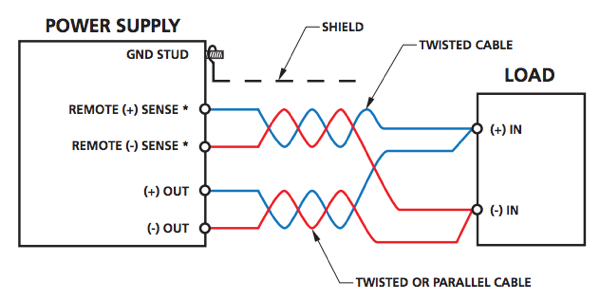 Figure 1. Both power leads and remote sense leads should be shielded, twisted pair cables that are as short as possible to avoid noise pickup.
Twisting the power leads also reduces the parasitic inductance of the cable. This improves the dynamic response characteristics of the power source by maintaining low source impedance at high frequencies. Keeping the inductance low also helps prevent high frequency voltage spikes at the load due to changes in the load current.
Another reason to keep inductance low is that the impedance between the output of the power supply and the load could make the ripple and noise at the load worse than the ripple and noise at the output of the power source. If this is a problem in your application, you may need to add bypass capacitors at the load terminals to bypass the high frequency load currents.
By choosing the right cable for both the power leads and the sense lines, you can deliver clean power to your DUT or system at the right voltage. For more information about using the remote sense capabilities of AMETEK Programmable Power sources, download the Remote Sensing application note.