
Many AC-powered products, such as switching power supplies and electronic lighting ballasts, draw high start-up currents to charge capacitive circuitry. Excessive inrush currents not only cause lights to flicker, but can also damage the unit. It's important, therefore, to be able to measure inrush currents to get a handle on this problem.
Traditionally, making this measurement required configuring a system made of several different instruments, including an AC power source, a power analyzer, a digital oscilloscope, and a high-frequency current probe. Acquiring and configuring this system can be costly, in terms of both time and expense. Fortunately, there is a better way. Modern AC power sources, such as California Instruments’ iX Series, have all the functionality needed to make this measurement with a single instrument.
The iX Series AC power sources have an integrated measurement system, with either two or six channels, that can be triggered by the source at any point on the input waveform. This eliminates the need for any additional equipment to make this kind of measurement. Not only does this provide a much faster way to set up and make this measurement, the measurement system offers 18-bit resolution, which is a higher resolution than many digital scopes on the market.
A typical measurement setup
To see how this works in practice, let's consider how you would measure the inrush current and current distortion for a compact fluorescent light ballast. For this example, we'll test a 28 W whose ballast electronics are integrated into the base of the bulb. Because testing the bulb requires only a single phase, you can use a 3001iX AC source. To control the test, we'll use a Windows PC with the instrument control software provided with the instrument.
To test the bulb, all you have to do is connect the load to the phase A terminals. No other connections are required. One channel of the 3001iX is configured to record the input voltage, while the other channel is configured to record the input current.
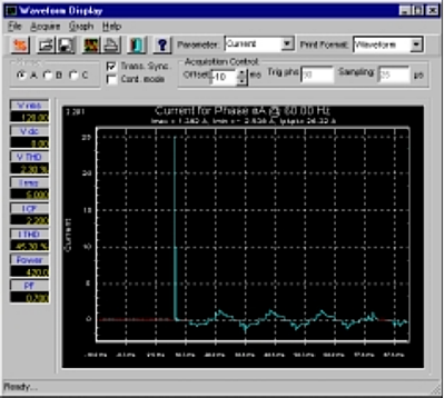 The peak inrush current measured for this test was 26.32 A.
To determine the maximum inrush current, you program the AC source to turn on 120 V RMS at 90°. This produces the maximum voltage slew rate on the ballast’s input. You also need to program the measurement system to begin measuring 10 ms or so before you turn on the voltage in order to capture the entire inrush current waveform.
The sampling rate for each channel is 40 ksamples/s. Because each channel can store 4,000 samples, the measurement system will show you what happens over a period of 100 ms. Figure 1 shows the current waveform captured by the 3001ix. As you can see the peak inrush current for this particular bulb is 26.32 A. The steady state current, on the other hand, is only 290 mA RMS.
For more information on this application, including how to measure the distortion caused by the load, download Application Note #115A, “Analyzing Peak Inrush Current using iX or iL Series”.