
To ensure that automotive electronics can withstand the voltage transients induced on the power bus, companies use expensive arbitrary waveform generation and coupling networks during the design phase. For production test, however, a simpler and less expensive means for simulating bus voltage variations and transients is required. For many transient tests, all you need is a switching power supply and an electronic load.
Here, we will show how to use an economical electronic load (eLOAD1 ) and SMPS DC supply to create a typical automotive power bus voltage transient for an automotive ECU test stand. In particular, this setup will generate a 12V to 4.5V transition in less than the 15 ms, a common specification for automotive testing. In addition, we will show how to configure a test system able to test multiple units under test (UUTs), each drawing up to 60 A.
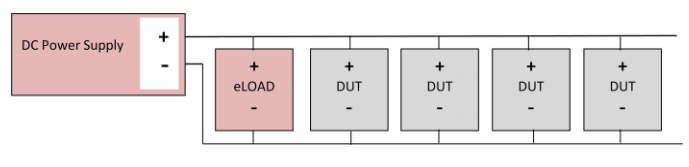
A block diagram of the test system is shown below. To supply power, the test system uses a programmable supply set at 14 VDC and operating in constant voltage mode with a current limit set to the sum of the max current for the UUTs. To generate the transient, the system uses a programmable electronic load to pull the bus voltage down to the levels required by the test.
To demonstrate the feasibility of this concept we connected a DLM40-15 power supply and an SLM 60-60-300 electronic load as shown in the block diagram. The electronic load is used in constant voltage (CV) mode. Using the load in this mode works because the load sets an impedance low enough to cause the power supply to change modes from constant voltage to constant current. In constant current mode, the power supply reduces its output voltage once the programmable current limit is exceeded. This method of generating transient voltages will work with any Sorensen DC supply that has automatic CV / CC mode crossover control.
For this demonstration, we used a fixed 1 ohm power resistor to simulate a single UUT load of 14 A at 14V. At the beginning of the test, the electronic load (in CV mode) was set at >15V, so it was effectively out of the circuit. At t=1, the load was switched to V=4.5V. At that point, the power supply switched to CC mode and the output dropped to the required level. In this test, the voltage dropped to 4.5 VDC in about 4 msec, well below the 15 ms specification.
Scaling up
To test more than a single UUT, we need a supply capable of supplying more current and a load that can dissipate more current. For example, to simultaneously test four UUTs, each drawing 60A, we had to consider the following:
- UUT load impedance = 14V/60A = 0.233 ohms.
- At 4.5V, IUUT = 4.5 V / 0.233 ohms = 19.3 A.
- The current flowing in the electronic load is Iload = Imax – IUUT = 60 A - 19.3 A = 40.7 A.
- The maximum dissipation, Pdiss = Iload X 4.5V = 183 W per DUT
To test 4 UUTs we would need an electronic load that could dissipate 4 x 183 W or 732 W. The power supply for this test system would need to deliver 240 A at 14V, or about 3,400 W. A good choice for the power supply would be the SGA 15X267 (15V at 267 A max), and a good choice for the load would be the SLH 60-240-1200 (60V, 240A, 1200W) max ratings. For additional current and power margin the SLH 60-360-1800 could be substituted.
For more information, download the application note, “Generating Fast Transient Voltage Test Profiles.” You can also contact AMETEK Programmable Power Sales at 858-458-0223 or email the Sales Department at sales.ppd@ametek.com.